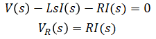
(eq. 1)
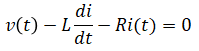
(eq. 2)
Transfer function and state space model are developed for a circuit with inductor and resistor in series as shown below.
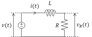
| (input) | v(t) | = | source voltage | |
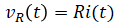
| (output) | vR(t) | = | voltage across resistor | unknowns |
| i(t) | = | current | ||
| L | = | inductance | ||
| R | = | resistance |
2 unknowns so 2 equations are needed.
Laplace transform (eq. 1) and (eq. 2):
Solve for the 2 unknowns:
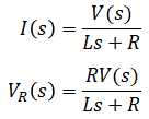
Find VR(s)/V(s):
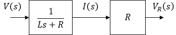
Use Laplace equations found in previous section to derive transfer functions from input voltage to current to output voltage:
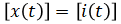
When an inductor is present in a system, current through the inductor is commonly chosen as a state variable. In this system, source voltage (input) and current through inductor are sufficient to determine this system's future voltage across the resistor (output). For these reasons, current is chosen as the state variable.
State vector:
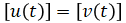
Input vector:
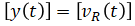
Output vector:
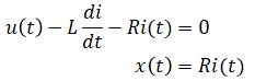
Rewrite (eq. 1) and (eq. 2) in these new notations:
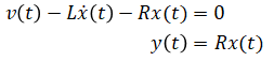
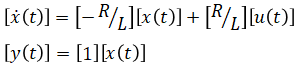
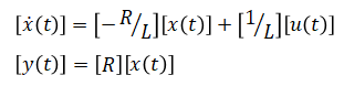
Rearrange equations to express ẋ(t) and y(t) in terms of x(t) and u(t):
A different state model of the same system is developed. Source voltage (input) and voltage across the resistor are also sufficient to determine this system's future voltage across resistor (output). Therefore, voltage across the resistor is now chosen as the state variable.
State vector:
Input vector:
Output vector:
Rewrite (eq. 1) and (eq. 2) in these new notations:
Rearrange equations to express ẋ(t) and y(t) in terms of x(t) and u(t) (by taking a derivative in the second equation):